
 EN



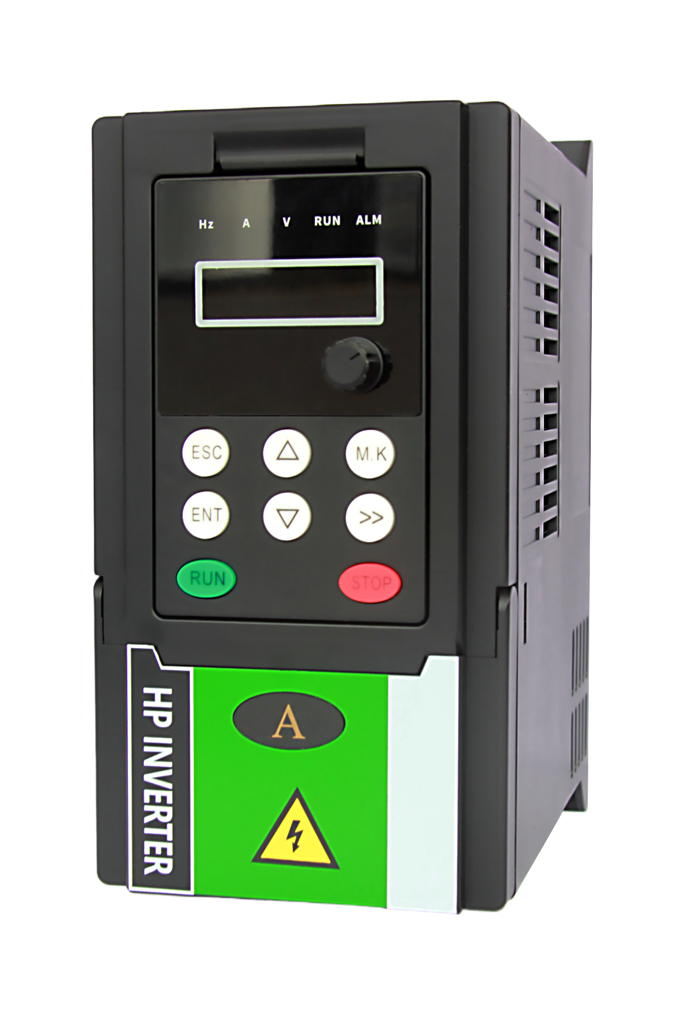
The Fundamental Physics Behind Variable Frequency Control
Understanding precise motor control begins with how alternating current interacts with magnetic fields. Variable frequency drives (VFDs) manipulate supply frequency to alter the speed of the rotating magnetic field—directly governing shaft rotational velocity. This relationship follows a well-defined electromagnetic principle, not a linear one.
Synchronous Speed, Slip, and Motor Response Dynamics
The synchronous speed of an AC induction motor is determined solely by supply frequency and pole count. For a 4-pole motor operating at 60 Hz, the theoretical no-load speed is exactly 1,800 RPM. In practice, the rotor always lags slightly behind this field—a phenomenon called slip, typically 2–5% under full load. Slip is essential: it induces rotor current, which generates torque. Without slip, no torque would be produced.
Modern VFDs exploit this dynamic. By adjusting output frequency, the drive shifts synchronous speed, causing instantaneous slip adjustment. Torque response follows the motor’s inherent slip-torque curve, and the rate of frequency change—known as ramp time—must be carefully tuned. Too-aggressive acceleration can push slip beyond the breakdown torque point, triggering instability or stall. Therefore, maintaining controlled slip within the motor’s stable operating region is critical for smooth, predictable speed transitions.
Why Maintaining a Stable V/f Ratio Is Essential for Torque Precision
Torque in an induction motor depends on air-gap magnetic flux, which is proportional to the voltage-to-frequency (V/f) ratio. If frequency drops without proportional voltage reduction, flux rises sharply—saturating the core, increasing losses, and degrading efficiency. Conversely, excessive voltage reduction weakens flux, collapsing torque output. At very low speeds, stator resistance dominates; many VFDs apply a “voltage boost” to compensate.
A constant V/f ratio ensures near-rated torque across the operating speed range. Field data shows that just a 5% deviation from the optimal ratio can reduce available torque by 15–20% at low frequencies (industry analysis, 2022). This precision is vital in torque-critical applications like hoists or extruders, where consistent force delivery must be maintained regardless of speed. By preserving stable flux, variable frequency control delivers energy-efficient, repeatable performance without sacrificing responsiveness.
Variable Frequency Drives: Core Architecture and Precision Tuning
PWM Strategy, Carrier Frequency Selection, and Dead-Time Compensation
Precise motor control originates in the inverter section’s Pulse Width Modulation (PWM) strategy. Using Insulated Gate Bipolar Transistors (IGBTs), the drive reconstructs an AC waveform from the DC bus by switching thousands of times per second. The modulation technique directly shapes harmonic content and torque ripple.
Higher carrier frequencies suppress audible noise and improve current waveform resolution—smoothing low-speed rotation. But they also increase IGBT switching losses, raising drive temperature and accelerating motor insulation stress. Critically, elevated carrier frequencies can trigger reflected wave phenomena that contribute to premature bearing failure.
Dead-time compensation is equally vital: a brief interval between turning off one IGBT and turning on its complementary device prevents destructive DC bus short circuits. Without compensation, this necessary delay distorts output voltage, causing torque pulsations and erratic behavior at low speeds. Advanced algorithms predict and correct this non-linearity, preserving sinusoidal current fidelity and ensuring consistent shaft rotation. Optimal carrier frequency selection—typically between 2 kHz and 16 kHz—balances thermal durability with mechanical dynamics.
Closed-Loop Performance: ±0.01% Frequency Accuracy in Modern VFDs
Open-loop VFD operation provides only a nominal speed reference; actual speed varies due to slip. Closing the loop with real-time feedback transforms the system into a high-precision speed and position regulator. Mounting an encoder or resolver directly on the motor shaft enables continuous comparison of actual versus commanded position.
Modern VFDs leverage this data to achieve frequency accuracy as tight as ±0.01%—a specification indispensable for coordinated multi-axis systems and precision spooling. The correction loop operates in microseconds, instantly compensating for load disturbances that would otherwise stall a motor near zero speed. Full torque at standstill—known as zero-speed servo lock—is essential for crane and hoist safety. This rigid synchronism eliminates the speed drift inherent in open-loop V/f control, ensuring exact conveyor matching in sequential manufacturing and protecting product integrity in sensitive processes like fiber drawing or film extrusion.
Grid Integration and Adaptive Frequency Synchronization
Seamless grid integration requires VFDs to maintain precise synchronization with utility frequency and phase angle. Grid disturbances—including harmonics, voltage sags, and frequency drift—can destabilize motor control, making rapid, accurate tracking essential. Even minor phase errors introduce circulating currents and mechanical stress.
Modern grid-connected converters use adaptive synchronization methods that respond in real time. Adaptive filters extract the fundamental grid frequency while rejecting noise, dynamically tuning parameters via feedback loops. Though highly effective, their computational demand often limits deployment to grids with severe variability.
Phase-locked loop (PLL) techniques remain the most widely adopted solution, offering an optimal balance of precision, resilience, and implementation simplicity. A well-tuned PLL locks onto the grid’s phase angle and detects frequency deviations within microseconds—enabling sub-cycle responses critical for active front-end drives and regenerative braking. Embedding these strategies allows VFD systems to operate stably across diverse grid conditions while meeting stringent interconnection standards.
Compliance, Safety, and Harmonic Management for High-Precision Variable Frequency Systems
NEC Article 430.122(B) and Sub-1% Tolerance Requirements
NEC Article 430.122(B) mandates that feeder and branch-circuit conductors supplying a VFD be sized based on the drive’s rated input current—not the motor’s nameplate full-load current. This accounts for the non-sinusoidal, harmonic-rich current drawn by the VFD’s rectifier stage, preventing conductor overheating and insulation degradation.
For high-precision systems, compliance with IEEE 519 (voltage THD <5%) is often insufficient. Critical process environments commonly require total current harmonic distortion (ITHD) below 1% at the point of common coupling. Achieving this sub-1% tolerance protects sensitive instrumentation, prevents nuisance tripping of protection relays, and preserves the VFD’s closed-loop frequency accuracy—typically ±0.01%—from harmonic-induced measurement errors.
Meeting such stringent limits demands advanced mitigation: multi-pulse rectifiers or active front-end drives paired with adaptive harmonic suppression algorithms. These solutions ensure both regulatory compliance and long-term operational safety and reliability.
FAQ Section
What is a Variable Frequency Drive (VFD) and how does it control motor speed?
A Variable Frequency Drive (VFD) controls motor speed by manipulating the frequency of the AC supply. Altering frequency influences the synchronous speed of the motor's rotating magnetic field, thereby controlling shaft rotation velocity.
Why is slip important in AC motors?
Slip is essential for inducing rotor currents that generate the torque needed for motor function. Without slip, the motor cannot produce torque.
How does maintaining a stable V/f ratio affect motor performance?
A stable V/f ratio ensures consistent air-gap magnetic flux, which is vital for optimal torque and efficiency. Deviations can lead to reduced torque and increased losses.
What is PWM and why is it used in VFDs?
PWM (Pulse Width Modulation) is a technique used in VFDs to reconstruct an AC waveform from the DC bus, ensuring precise motor control and harmonic suppression.
What challenges arise when integrating VFDs with the grid?
Grid disturbances such as harmonics and frequency drift can destabilize motor control. Techniques like adaptive synchronization and phase-locked loops (PLL) help maintain precise grid integration.