
 EN
EN



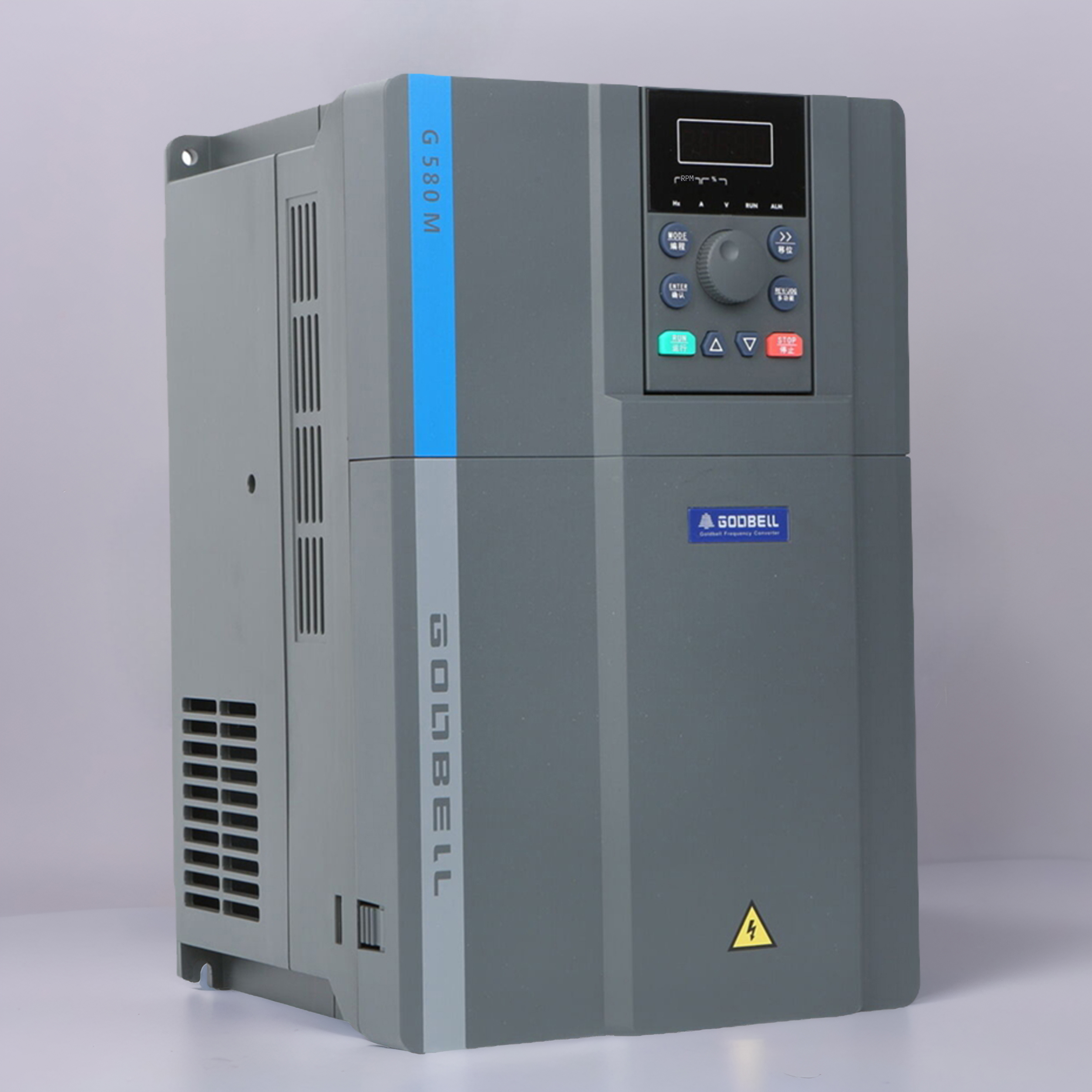
Sizing Your Single to 3 Phase Converter Accurately
Calculating Total Kilowatt Demand and Motor Inrush Considerations
Selecting the correct single to 3 phase converter begins with a precise calculation of your total load—not just the horsepower rating of the largest motor. A common field error is sizing solely on the nameplate of the primary motor, which overlooks auxiliary control transformers, coolant pumps, or resistive loads that draw real power in kilowatts (kW). The total kW demand is the aggregate of all components operating simultaneously. Once established, the critical factor becomes the starting current—or inrush—of the hardest-starting motor. When a 3-phase motor starts across the line, it draws 5 to 8 times its full-load amperage for a brief moment. A phase converter must supply this instantaneous surge without voltage sag that could stall the motor or damage sensitive electronics. For CNC machinery, inrush demands are especially high due to rapid spindle acceleration. Insufficient surge capacity can raise motor winding temperature by up to 30%, accelerating insulation degradation by half—a finding corroborated by IEEE standards (IEEE Std 112-2021). To ensure stability during the high-impedance startup phase, multiply the largest motor’s full-load amperage by 3, then add the full-load amperage of all other motors. This yields the minimum single-phase input current the converter must support.
Selecting Between Rotary and Static Single to 3 Phase Converters by Load Profile
The nature of the driven load dictates whether a rotary or static single to 3 phase converter is appropriate—these are fundamentally different technologies. A static converter functions as an electronic starter: it uses capacitors to generate a third phase only during startup, after which the motor runs on single-phase power and delivers roughly two-thirds of its rated horsepower. It suits simple, constant-torque loads like basic drill presses or grinders where reduced output is acceptable. In contrast, a rotary converter acts as a true power generator. Using a rotating idler motor-generator, it produces a continuous, balanced three-phase output, enabling motors to deliver full rated power. For variable-torque, high-inertia, or frequently cycled loads—such as lathes, milling machines, or reciprocating air compressors—a rotary converter is essential. Installing a static unit for such applications risks poor performance, overheating, and eventual motor failure. The table below summarizes key selection criteria:
| Load Profile | Suitable Converter Type | Key Reason |
|---|---|---|
| Single, simple motor (e.g., drill press) | Static | Runs at constant speed; tolerates reduced power output. |
| Multiple motors or variable torque (e.g., CNC lathe) | Rotary | Delivers full-rated power and supports coordinated multi-motor start-up. |
| High-inertia, hard-starting (e.g., reciprocating compressor) | Rotary | Provides sustained surge capacity to overcome massive inrush without stalling. |
Verifying Electrical Service Compatibility
Confirming Single-Phase Supply Voltage, Amperage, and Circuit Capacity
Before energizing a single to 3 phase converter, conduct a precise survey of the existing electrical infrastructure. Begin by measuring idle supply voltage with a true RMS multimeter to verify it falls within the tolerance specified on the converter’s nameplate. Service capacity isn’t defined by available breaker slots alone—it requires calculating continuous load. As noted in guidance from leading manufacturers, a converter’s single-phase input current draw may reach 1.5 times its nominal three-phase output rating. Therefore, the dedicated breaker must be sized at 125% of the converter’s maximum input amperage to prevent nuisance tripping during motor inrush. Industry data confirms that voltage drops exceeding 3% under load sharply increase operating temperature, degrading internal capacitors and shortening service life. The panel must have sufficient headroom: a qualified electrician should verify that bus rating and main feeder conductors can accommodate the added load without exceeding 80% of circuit capacity.
Ensuring Grounding Integrity and NEC Compliance for Single to 3 Phase Converters
Proper grounding is a non-negotiable safety requirement—not a procedural formality. The equipment grounding conductor must be sized per NEC 250.122, based on the overcurrent protection device rating, and routed in the same conduit as phase conductors to maintain a low-impedance fault path. A frequent compliance violation involves bonding the manufactured neutral to the grounding electrode at the converter, creating a parallel path for normal return current—a direct violation of NEC 250.6. Instead, the converter case must be bonded to the system ground to keep touch potential safe during a fault. NEC 110.26 mandates a clear working space of at least 36 inches in front of the panel to allow safe, rapid disconnection. All metallic raceways and enclosures require effective bonding to prevent hazardous potential differences during transient voltage events. Finally, the installation must include a lockable disconnect switch within sight of the unit, enabling service personnel to perform zero-energy verification before maintenance.
Wiring, Commissioning, and Performance Validation
Step-by-Step Wiring Sequence for Rotary Single to 3 Phase Converters
When wiring a rotary single to 3 phase converter, strict adherence to connection sequence prevents voltage imbalances and premature failure. Follow these steps only after locking out and verifying de-energization of the main supply breaker:
- Mount and ground the converter – Secure the enclosure near the single-phase panel. Bond the grounding lug to the facility ground electrode system using a continuous copper conductor sized per NEC 250.122.
- Connect the single-phase input – Bring L1, L2, and the equipment ground from the dedicated circuit breaker to the converter’s “L1” and “L2” input terminals. Torque connections to the manufacturer’s specification—typically 20–25 in-lbs for lug-style terminals.
- Wire the idler motor (if separate) – For open-frame units, connect idler leads to the converter’s motor terminals per the nameplate diagram. Use wire gauge matching the converter’s output rating, and verify rotation direction before final tightening.
- Terminate the three-phase output – Run conductors from T1, T2, and T3 to the three-phase load panel or disconnecting means. The generated leg (commonly T3—the “wild” leg) must be marked with orange tape and connected only to 240 V three-phase loads—not to single-phase circuits.
- Install overcurrent protection – Place a three-pole breaker or fused disconnect at the load panel, sized at 125% of the converter’s full-load output current per NEC 455.7.
- Re-check every connection – Ensure no loose strands contact the enclosure and confirm phase conductors are not crossed. Energize briefly with no load to verify smooth idler motor startup and operation.
A structured commissioning plan—including loop checks and functional tests—uncovers wiring faults before they escalate into operational failures. Only after validation should load equipment be connected.
Measuring Voltage Balance and Phase Spread Under No-Load and Full-Load Conditions
Voltage balance is the most critical indicator of a rotary single to 3 phase converter’s operational health. Per NEMA MG1, maximum allowable voltage imbalance for three-phase motors is 5% (NEMA MG1-2023); exceeding this accelerates winding insulation breakdown. Verify compliance using a true-RMS multimeter rated for 1000 V CAT III. Measure phase-to-phase voltages (A-B, B-C, C-A) first with no load, then again under full-load conditions. Calculate imbalance as:
[ \text{Imbalance %} = \frac{\text{Max deviation from average}}{\text{Average voltage}} \times 100 ]
A well-balanced system typically shows <2% deviation. Phase spread—the angular separation between phases—should remain 120° ± 2°; a power quality analyzer provides accurate measurement. If imbalance exceeds 5% under full load, inspect for loose connections, undersized input wiring, or an overloaded idler motor. Document all readings in a commissioning log: these establish a baseline for predictive maintenance and demonstrate compliance with NEC performance requirements prior to handover.
Frequently Asked Questions (FAQ)
What is the main difference between a rotary and static single to 3 phase converter?
A static converter generates a third phase only during startup, while a rotary converter produces continuous, balanced three-phase output. Rotary converters are ideal for high-inertia or variable torque loads, whereas static converters are suited for simple, constant torque applications with reduced power requirements.
How do I calculate the correct size for my single to 3 phase converter?
The sizing process involves calculating the total kilowatt demand of all components operating simultaneously and considering the inrush current of the hardest-starting motor. For accurate sizing, multiply the largest motor's full-load amperage by 3 and add the amperage of other motors to determine the minimum input current.
What is voltage sag, and why is it critical for phase converters?
Voltage sag refers to a temporary drop in voltage during motor start-up, which can stall motors or damage electronics. Phase converters must handle inrush currents without significant voltage sag to ensure safe and efficient operation, especially for equipment like CNC machinery.
What steps should I take to verify my electrical service compatibility?
Measure idle supply voltage with a true RMS multimeter, verify that the breaker is sized adequately, confirm the bus rating, and ensure the main feeder conductors can handle the added load without exceeding 80% circuit capacity.