
 EN
EN



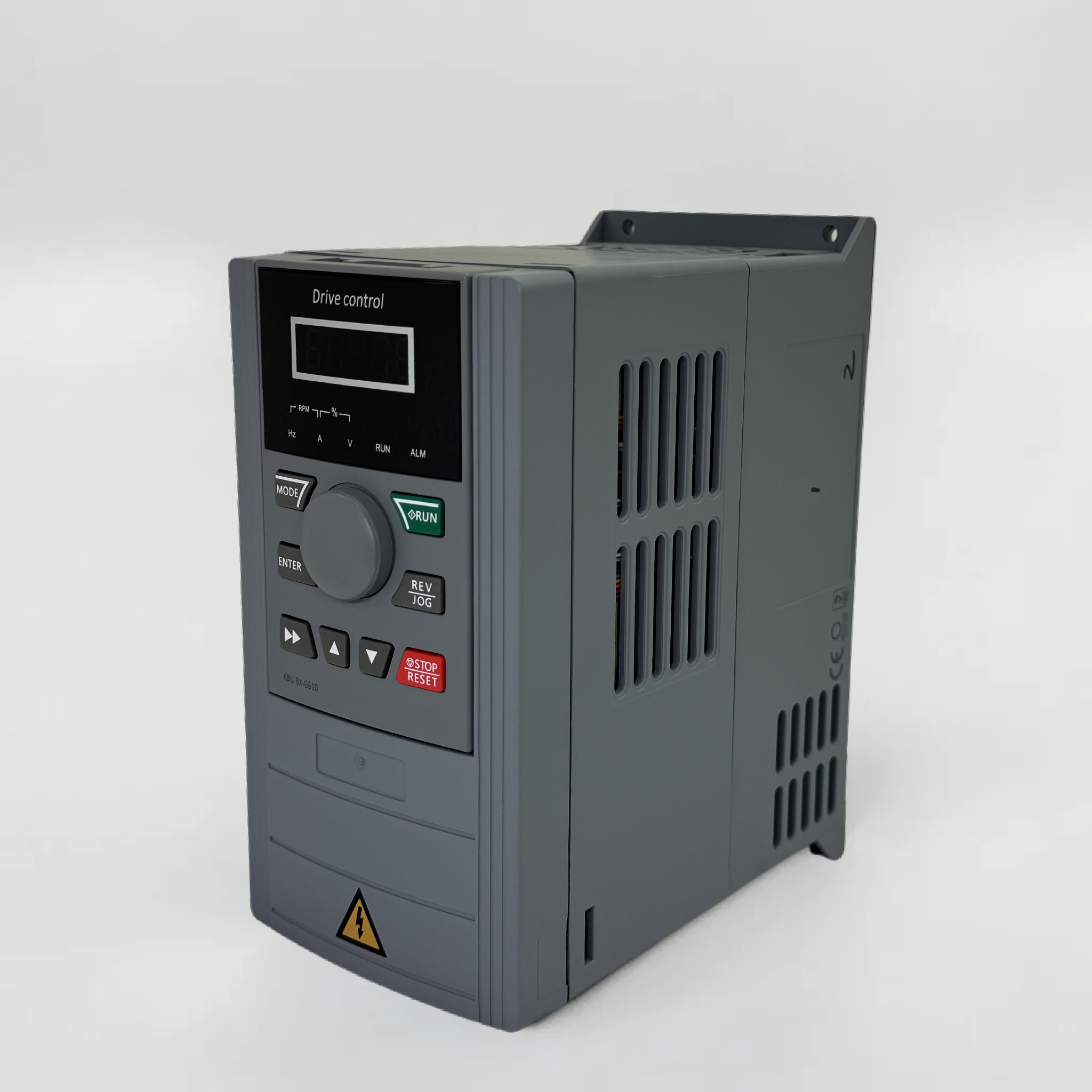
Maximize Solar Inverter Efficiency with Adaptive MPPT Tuning
How MPPT algorithms dynamically respond to irradiance and temperature fluctuations
Maximum Power Point Tracking (MPPT) is the intelligence inside a modern solar inverter that continuously hunts for the optimal voltage–current combination to extract the most power from the solar array. Solar panels exhibit a non-linear power curve that shifts dramatically with changing irradiance and cell temperature: under reduced sunlight or passing clouds, the maximum power point (MPP) moves to a lower voltage; as panels heat up, MPP voltage drops while current rises slightly. An MPPT algorithm samples panel output every few milliseconds and commands the DC–DC converter to adjust operating impedance—keeping the system precisely aligned with the shifting MPP.
Laboratory testing of high-quality string inverters shows MPPT tracking efficiency exceeding 99.5% under varied conditions—meaning less than 0.5% of available energy is lost during optimization. Industry studies confirm MPPT-equipped inverters harvest 20–25% more energy annually than systems without active tracking, with gains surpassing 45% during cold, low-irradiance winter months. This dynamic responsiveness enables consistent yield across seasons and weather patterns.
Perturb & Observe vs. Incremental Conductance: Performance trade-offs for residential and commercial solar inverters
Two MPPT algorithms dominate the market: Perturb & Observe (P&O) and Incremental Conductance (IC). P&O works by periodically nudging the operating voltage and measuring the resulting power change—if power increases, it continues in that direction; if not, it reverses. Its simplicity, low computational load, and cost-effectiveness make it standard in residential string and microinverters. However, P&O inherently oscillates around the MPP and can mis-track during rapid irradiance changes—such as fast-moving cloud cover—leading to temporary energy loss.
Incremental Conductance avoids oscillation by calculating dP/dV from the I–V curve and stopping perturbation when the derivative equals zero—the definitive sign of the true MPP. While more computationally intensive and typically reserved for premium commercial and utility-scale inverters, IC delivers superior stability under partial shading and thermal hotspots. Field data shows IC recovers the MPP 30% faster than P&O during transient events. For typical residential rooftops with modest shading, a well-tuned P&O algorithm achieves over 99% of the energy harvest possible with IC—making the added cost unnecessary. In contrast, large commercial arrays benefit meaningfully from IC’s accuracy: annual energy gains of 2–4% over P&O-based systems are routinely observed where shading, reflector effects, or complex string layouts challenge simpler algorithms.
Right-Size Your Solar Inverter with Optimal Loading Ratio
Calculating ideal inverter loading ratio (ILR) for rooftop, ground-mount, and utility-scale solar inverters
The inverter loading ratio (ILR)—defined as DC array capacity divided by AC inverter rating—is a critical design lever that directly shapes both energy yield and project economics. Optimal ILR depends on site-specific factors including irradiance profile, panel orientation, soiling, and temperature derating. Typical ranges cluster by installation type:
| Installation Type | Typical ILR Range | Key Considerations |
|---|---|---|
| Rooftop residential | 1.15–1.30 | Space constraints and variable shading favor slightly higher ILR to boost low-light production. |
| Ground-mount commercial | 1.20–1.35 | Open terrain allows consistent tilt; ILR can be tuned to balance clipping and inverter cost. |
| Utility-scale | 1.30–1.50 | Economies of scale support aggressive oversizing; land availability and interconnection limits often define the upper bound. |
A 2023 field analysis by a national laboratory found that a 1.25 ILR delivered 99% of the theoretical maximum annual energy for a mid-latitude rooftop system—while increasing to 1.50 yielded just 0.8% more, due to escalating clipping losses. Designers begin with the array’s Pmp at standard test conditions, then apply real-world loss factors (soiling, mismatch, thermal coefficient) before iterating with hourly simulation software to identify the ILR where marginal panel cost equals marginal energy value.
Balancing clipping losses against underutilization: When oversizing delivers net energy gain
Clipping occurs when DC output exceeds the inverter’s AC limit—truncating peak power. Yet moderate oversizing often yields net energy gain because inverters operate more efficiently across a broader load range. A 2022 study by a leading European research institute measured a 1.33 ILR system in a sunny climate delivering 1.9% more annual energy than a 1.0 ILR baseline—even with 2.1% of potential energy clipped. Clipping losses are confined to brief, high-irradiance windows, whereas gains from improved low-light performance and reduced underutilization accrue throughout the day.
Underutilization—running an inverter significantly below its rated capacity—lowers efficiency: most inverters reach peak conversion efficiency between 30% and 70% of rated load. Oversizing the DC array keeps the inverter operating within this sweet spot longer, offsetting clipped energy. Economic modeling confirms the optimal ILR is typically 1.2–1.3 for residential and commercial systems, where panel costs are relatively low and the value of each additional kWh remains high.
Unlock Real-World Gains Through Solar Inverter Firmware and Configuration Updates
Firmware impact on harmonic distortion, reactive power support, and nighttime standby consumption
Modern solar inverter firmware governs far more than basic DC–AC conversion. Updates refine switching algorithms to reduce total harmonic distortion (THD) to well below 3%, with premium residential models now achieving <1% THD—enhancing grid compatibility and reducing stress on downstream equipment. Reactive power control has also matured: firmware now enables dynamic VAR injection or absorption to stabilize local voltage and comply with evolving grid codes—eliminating the need for external reactive compensation hardware. Nighttime standby consumption has dropped significantly, too: while older inverters drew 5 W or more when idle, firmware-driven deep-sleep modes now reduce this to under 1 W—saving kilowatt-hours cumulatively over the system’s lifetime. These improvements are validated in field deployments, where over-the-air updates recalibrate power electronics and communication logic—unlocking measurable efficiency gains without hardware changes.
Validated efficiency uplift: Enphase IQ8+ v4.12 improves weighted solar inverter efficiency by 2.3% (IEC 62600-1)
The Enphase IQ8+ microinverter firmware update v4.12 demonstrated a 2.3% increase in weighted CEC efficiency per IEC 62600-1 testing protocols—a result of refined MPPT response and reduced conversion losses. This improvement translates directly into higher energy yield from the same array. Such validation underscores that firmware is not merely maintenance—it’s a strategic performance lever. For asset owners, this 2.3% efficiency gain shortens payback periods and lifts annual production with zero capital expenditure.
FAQ
What is MPPT and why is it important for solar inverters?
MPPT, or Maximum Power Point Tracking, is a technology in solar inverters that optimizes the power output by constantly adjusting to the ideal voltage-current combination. It ensures systems achieve peak efficiency by adapting to changes in sunlight and temperature.
What are the key differences between Perturb & Observe and Incremental Conductance algorithms?
Perturb & Observe (P&O) is simple and cost-effective, making it ideal for residential systems, but it can oscillate around the maximum power point during rapid sunlight changes. Incremental Conductance is more computationally intense and better for commercial systems, as it calculates the true maximum power point more accurately, especially during shading or transient conditions.
What is the ideal inverter loading ratio (ILR) for different solar installations?
For residential rooftops, typical ILR ranges are 1.15–1.30. Ground-mounted commercial installations fall in the 1.20–1.35 range, and utility-scale systems are generally between 1.30–1.50, depending on location-specific factors like shading and irradiance.
How does oversizing a solar inverter lead to gains despite energy clipping?
Oversizing a solar inverter results in net energy gains by improving low-light performance and reducing underutilization. While energy loss may occur during peak sunlight, the broader operational efficiency over a day offsets this.
How do firmware updates improve solar inverter performance?
Firmware updates enhance efficiency by reducing harmonic distortion, supporting reactive power, and cutting nighttime standby consumption. They can also recalibrate MPPT algorithms, leading to higher annual energy yields without additional hardware costs.
Table of Contents
- Maximize Solar Inverter Efficiency with Adaptive MPPT Tuning
- Right-Size Your Solar Inverter with Optimal Loading Ratio
- Unlock Real-World Gains Through Solar Inverter Firmware and Configuration Updates
-
FAQ
- What is MPPT and why is it important for solar inverters?
- What are the key differences between Perturb & Observe and Incremental Conductance algorithms?
- What is the ideal inverter loading ratio (ILR) for different solar installations?
- How does oversizing a solar inverter lead to gains despite energy clipping?
- How do firmware updates improve solar inverter performance?