
 EN
EN



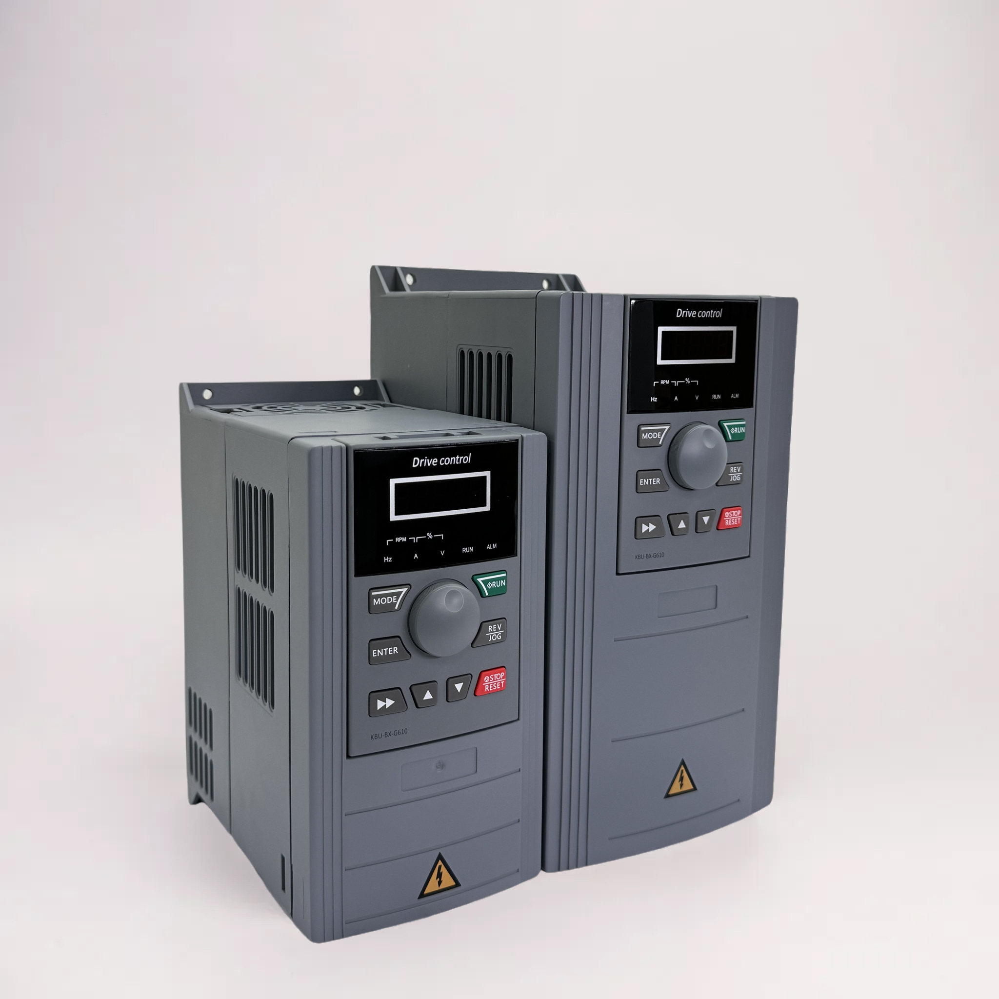
Configure MPPT Settings for Maximum Solar Energy Harvest
Matching MPPT voltage range to PV string configuration and temperature coefficients
The MPPT (Maximum Power Point Tracking) algorithm in a solar pump inverter must continuously locate the voltage–current pair at which the PV array delivers peak power. For reliable tracking, the inverter’s MPPT voltage window must fully encompass the string’s Vmp range across all operating temperatures. Crystalline silicon modules typically lose 0.3–0.5% of voltage per °C rise above 25 °C. For example, a 10-module series string with a 300 V Vmp at standard test conditions may drop to ~255 V at 75 °C cell temperature. If the inverter’s lower MPPT limit is set above this value, tracking stalls and energy harvest collapses. To prevent this, configure the minimum MPPT voltage to sit 10–15% below the string’s expected hot-weather Vmp—and set the upper limit high enough to capture cold-morning voltage spikes. Field data from off-grid irrigation systems confirm that a correctly matched voltage window sustains MPPT tracking at 99% of instantaneous maximum power; a 20 V mismatch can reduce daily energy capture by 7–12% [source: IRENA Off-Grid Solar Pumping Performance Database, 2022].
Leveraging high MPPT efficiency (98.5–99.2%) to boost daily water yield: real-world data from off-grid farms
MPPT conversion efficiency directly determines how much harvested solar energy reaches the pump motor. Modern solar pump inverters achieve 98.5–99.2% MPPT efficiency using wide-bandgap semiconductors and fast digital control—up from 93–96% in legacy units. This 3–5 percentage point gain yields tangible increases in water output. A 2023 multi-farm trial across sub-Saharan Africa found that replacing a 94%-efficient inverter with a 99%-efficient unit increased daily pumped volume by 5.2%—an additional 18 m³/day from a 5 kW array. Over a 90-day dry season, cumulative gains exceeded 1,600 m³, sufficient to irrigate an extra 0.4 hectare of vegetables. The benefit is most pronounced during low-irradiance periods (early morning and late afternoon), when high-efficiency MPPT maintains pump operation longer and at higher speeds without compromising stability.
Tune VFD Parameters to Align with Pump Hydraulics and Load Dynamics
Optimizing output frequency (25–75 Hz) and torque boost to maximize volumetric flow across head ranges
The VFD controls motor speed by adjusting output frequency. Centrifugal pumps operate most efficiently between 25 and 75 Hz—within this range, flow scales linearly with frequency, while head varies with the square of speed. Setting the frequency limits to match the pump’s mechanical and thermal envelope is essential: operation below 25 Hz risks inadequate motor cooling; above 75 Hz increases cavitation risk and mechanical stress. Apply torque boost (a 5–8% voltage increase below 30 Hz) to compensate for reduced voltage and ensure smooth startup under high static head. Fine-tune based on real-time power and flow measurements—not theoretical curves. For centrifugal loads, use a quadratic V/F curve (squared torque) to align with hydraulic demand and minimize energy waste at partial load. Field validation shows optimized frequency and torque settings improve daily water output by 12–18% under variable irradiance, keeping the pump closer to its best efficiency point across diverse head conditions.
Setting safe DC voltage thresholds—low-voltage cut-off and overvoltage protection—to protect the solar pump inverter and motor
DC bus voltage fluctuates with irradiance, so precise voltage thresholds are critical for system longevity. Set the low-voltage cut-off to prevent motor overheating and unstable operation: for 48 V systems, use 42–44 V; for 380 V systems, set it near 300 V—just above the motor’s minimum torque threshold. Overvoltage protection guards against cloud-edge transients and rapid load shedding. Configure the trip point at 10–15% above the array’s STC open-circuit voltage (e.g., 460 V for a 400 V array), with a 1–2 second delay to avoid nuisance tripping. These calibrated thresholds protect power electronics and motor insulation, significantly reducing unplanned downtime and repair costs. Properly set limits also mitigate thermal cycling stress—extending inverter service life by up to 30%, per field reliability studies conducted by the Solar Pumping Association of India (2021).
Enable Intelligent Dry-Run Protection via Sensor Integration
Calibrating water level or pressure sensors for reliable dry-run shutdown (analog 0.3–0.8 V / Modbus register mapping)
Dry-run protection depends entirely on accurate sensor input. Analog water level sensors commonly output 0.3–0.8 V to indicate low-fluid conditions. Calibration involves mapping this voltage span to the inverter’s dry-run threshold—either through analog parameter settings or Modbus register mapping for digital sensors. In the latter case, the measured value is read into a designated holding register and compared against a user-defined trip point. Field experience shows that setting the trip threshold at 0.5 V reliably triggers shutdown before air enters the pump casing—preventing seal damage, bearing wear, and impeller erosion. Always verify the sensor’s output range against the inverter’s analog input specification (e.g., 0–1 V or 4–20 mA) to avoid false positives or delayed response.
Choosing between pressure-switch and current-sensing detection: reliability, maintenance, and aquifer-specific trade-offs
Dry-run detection can be implemented via pressure switch or motor current monitoring—each suited to different hydrogeological contexts.
| Detection Method | Reliability | Maintenance Needs | Aquifer Suitability |
|---|---|---|---|
| Pressure switch | High – mechanical snap-action resists electrical noise | Occasional diaphragm cleaning; contacts rated for ≥100 k cycles | Best for boreholes with stable water columns; less responsive to rapid drawdown in fractured or low-yield aquifers |
| Current-sensing (via VFD) | High – detects loss of hydraulic load within 0.1 s | None; fully software-based, no moving parts | Ideal for deep, variable-yield, or silty aquifers; distinguishes dry-run from partial clogging or pipe blockage |
While pressure switches offer simplicity and low upfront cost, they require periodic servicing in turbid water and may miss early-stage drawdown. Current-sensing—built into virtually all modern solar pump inverters—is maintenance-free, highly responsive, and adaptable to site-specific aquifer behavior. For new installations or wells with uncertain yield dynamics, current-based detection is strongly recommended as the default solution.
FAQs
What is the role of MPPT in solar pump inverters?
MPPT (Maximum Power Point Tracking) ensures the PV array operates at its peak power output by continually adjusting voltage and current levels. Correctly configured MPPT settings maximize energy harvest, even under varying temperatures.
Why is high MPPT efficiency crucial in solar pump systems?
High-efficiency MPPT enables more energy to reach the pump motor, boosting water yield. Systems with MPPT efficiency above 98.5% perform better, especially during low-irradiance periods.
How does adjusting VFD parameters improve pump performance?
Fine-tuning output frequency and applying torque boosts optimize motor speed and flow rates, ensuring efficient operation across different hydraulic load conditions.
What are the benefits of current-sensing over pressure switches for dry-run detection?
Current-sensing is maintenance-free, highly responsive, and ideal for aquifers with variable yield dynamics, while pressure switches require servicing and struggle with early-stage drawdowns.
How do voltage thresholds protect the inverter and motor?
Low-voltage cut-offs and overvoltage protection settings prevent motor instability and protect electronic components from stress, enhancing system reliability and longevity.
Table of Contents
- Configure MPPT Settings for Maximum Solar Energy Harvest
- Tune VFD Parameters to Align with Pump Hydraulics and Load Dynamics
- Enable Intelligent Dry-Run Protection via Sensor Integration
-
FAQs
- What is the role of MPPT in solar pump inverters?
- Why is high MPPT efficiency crucial in solar pump systems?
- How does adjusting VFD parameters improve pump performance?
- What are the benefits of current-sensing over pressure switches for dry-run detection?
- How do voltage thresholds protect the inverter and motor?